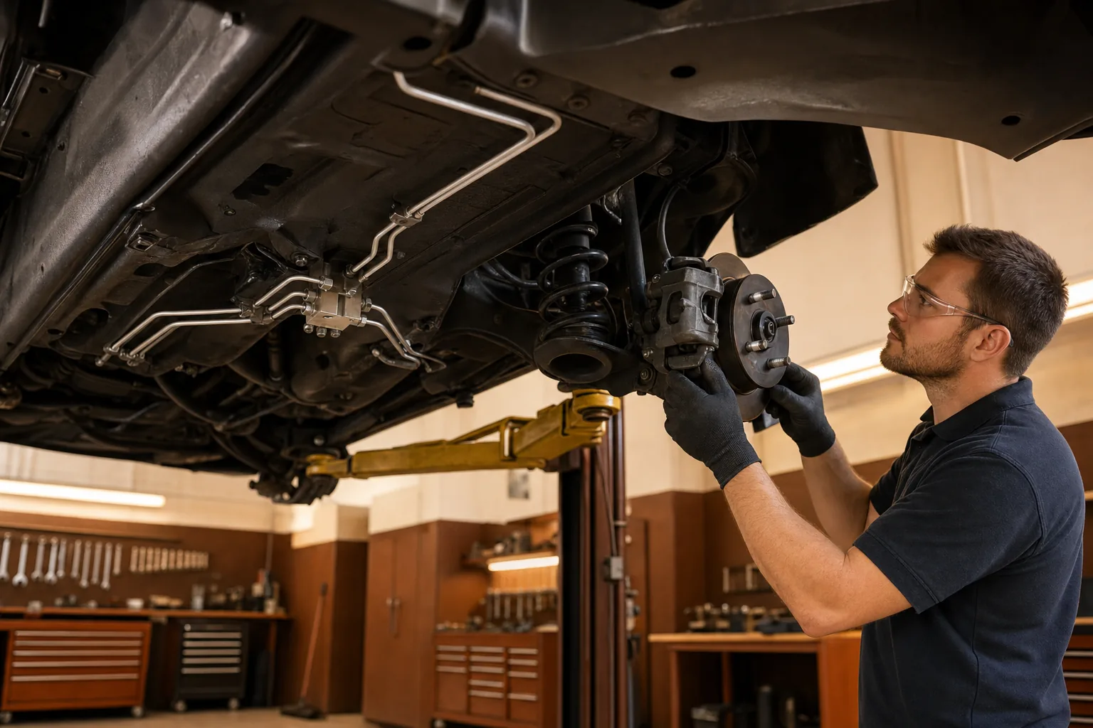
Split hydraulic brake circuits are designed to keep partial braking capacity if one circuit fails. That safety advantage also makes imbalance harder to detect — the pedal can feel firm while one side of the vehicle carries a disproportionate share of the load.
Symptoms That Mislead Technicians
Owners often describe brake fade, mild pull, or a pedal that feels normal at rest but softens after repeated stops. Shops frequently replace pads and rotors because wear patterns look uneven. Without circuit-level testing, the underlying hydraulic split remains unchecked.
At ultramicrox, we treat pad thickness as a data point — not a diagnosis. Uneven pad wear frequently traces to seized caliper guides, contaminated fluid in one circuit, or a proportioning valve that no longer meters pressure correctly under load.
Circuit-Level Testing Sequence
Step 1: Line Lock Isolation
We isolate front and rear circuits using approved line-lock tools at the master cylinder outlets. Pedal travel and firmness are recorded for each circuit independently. A circuit that requires noticeably less pedal effort to hold pressure often indicates internal leakage or flex elsewhere in that loop.
Step 2: Proportioning Valve Verification
Proportioning valves modulate rear circuit pressure relative to the front under high deceleration. Static bench tests miss dynamic behavior. We apply controlled pedal pressure while monitoring clamp load at each corner with calibrated gauges.
Step 3: Caliper Guide Inspection
Guide pins and slide surfaces must move freely under load. Corrosion behind dust boots is common on vehicles that see seasonal road salt. We disassemble, measure pin diameter, and replace hardware rather than lubricating contaminated assemblies.
Documenting Findings Before Repair
Every brake diagnosis at our Chicago workshop includes a written scope: which circuit showed imbalance, measured clamp differences, and whether hardware or hydraulics drive the failure. Clients approve the scope before parts are ordered.
- Record pedal height and firmness per circuit
- Photograph guide pin condition before disassembly
- Verify fluid condition separately in each reservoir section where applicable
- Bedding procedure documented after reassembly
Key Takeaway
Dual-circuit architecture adds a layer of safety and a layer of diagnostic complexity. Replacing friction material without tracing hydraulic balance leaves the root cause intact. Methodical circuit testing separates a lasting repair from a temporary pad swap.